
 EN
EN  Romana
Any precise measurement starts with a correct alignment. If the datum reference frame (Datum System) is wrong, absolutely all the results you report will be compromised. But what does it actually mean to lock the degrees of freedom of a part, and why do CMM programs give us different results depending on the chosen standard?
In this article, we will decode the math behind coordinate systems and explore the subtle yet critical differences between the ISO and ASME standards.
1. The Basic Rule: The 6 Degrees of Freedom
In three-dimensional space, any unrestrained part has 6 degrees of freedom:
-
3 Translations: Linear movements along the X, Y, and Z axes.
-
3 Rotations: Rotational movements around the X, Y, and Z axes.
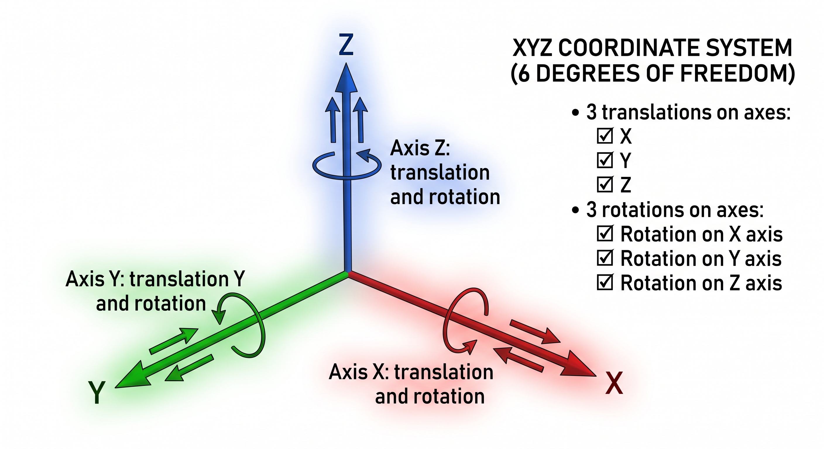
The golden rule in GD&T is the following: any datum feature locks all applicable degrees of freedom, depending on its geometry and its position in the datum reference frame.
2. The Strict Hierarchy: Primary, Secondary, and Tertiary Datums
The most common datum system consists of three planes, which define the coordinate system of the workpiece. To understand how it works, let's take a practical example: a machined block where we need to inspect the position of a hole relative to an A|B|C datum reference frame.
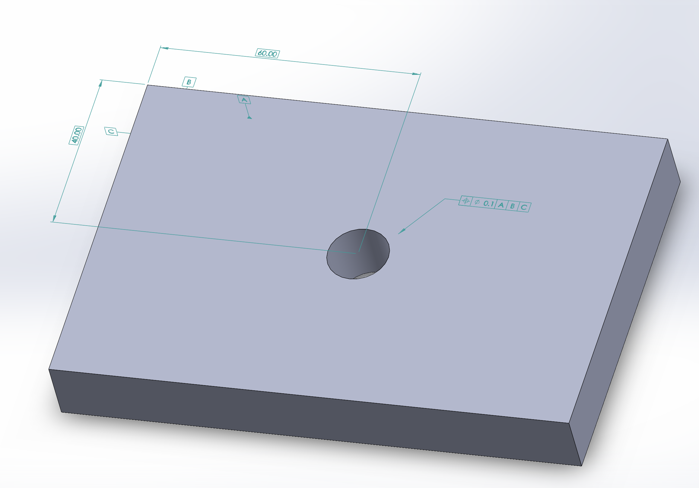
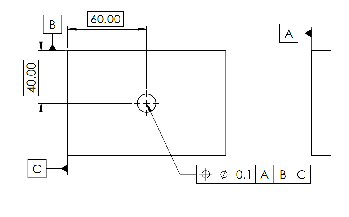
The hole has a basic dimension (theoretically exact position) of 60 mm relative to datum C and 40 mm relative to datum B.
Here is how the coordinate measuring machine (CMM) physically and mathematically approaches this reference frame:
-
Primary Datum (A): The CMM probes the surface and determines an outer tangential plane. In the ISO system, this is calculated by minimizing the maximum distance from the extracted points, using a Chebyshev association with an outside material constraint. It then constrains 2 rotations and 1 translation. If we assume that datum A has its surface normal oriented along the Z axis, then the 2 rotations are around the X and Y axes, and the translation is constrained along the surface normal, namely the Z axis.
-
Secondary Datum (B): This is where the hierarchy steps in! Plane B is not just any plane; it must be an outer tangential plane calculated with an orientation constraint (strictly perpendicular to plane A). Assuming that datum B has its surface normal oriented along the Y axis, it will constrain the last rotation around the Z axis and the translation along its own axis, namely the Y axis.
-
Tertiary Datum (C): This plane must respect two orientation constraints: it must be perfectly perpendicular to both plane A and plane B. Datum C will constrain the final translation, along the X axis.
-
Thus, all 6 degrees of freedom have been constrained by the coordinate system built from the ABC datums.
Once this system is locked, the tolerance zone for the hole becomes a cylinder fixed at the basic dimensions of 60 mm and 40 mm, strictly perpendicular to plane A.
3. LSQ vs. ISO 5459: How Do CMM Softwares Calculate Datums?
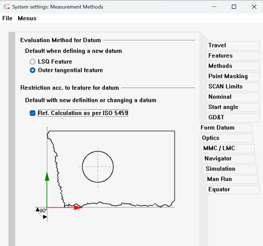
In most 3D measurement software (such as ZEISS Calypso), the default calculation for a new datum feature is set to LSQ (Least Squares / Gauss). If we want the datum system to strictly respect the hierarchy and the outer contact defined by the standard, we must explicitly activate the "Ref. Calculation as per ISO 5459" option.
There is a fundamental mathematical and physical difference between the two approaches: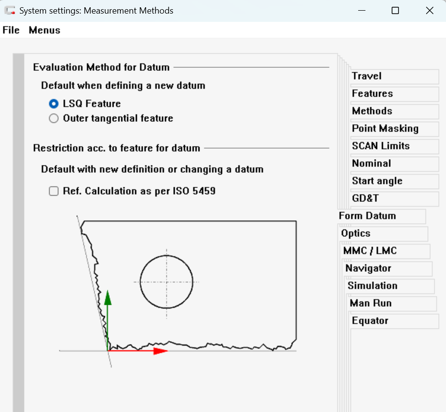
The Default Method (LSQ / Gauss): The software first associates a mean plane to each surface using the least squares method. When building the coordinate system, the hierarchy and orientation constraints are applied to these independently calculated planes.
-
The ISO 5459 Method (Outer Tangential & Constrained): The software enforces that the planes used for the origin of the datum system are strictly perpendicular to each other (exactly 90º) right from the association phase. The secondary plane is no longer calculated freely on its own surface, but is forced to 90º relative to the primary plane and only then is it brought tangent to the outside of the material (at the highest peaks).
-
The choice between LSQ and ISO 5459 has a direct impact depending on the manufacturing technology of the part:
-
Milled / Ground Metal Parts: Form deformations and perpendicularity deviations between faces are usually in the micron range. In this case, the difference between an LSQ alignment and an ISO 5459 one is practically imperceptible, with both methods generating almost identical results.
-
Injection Molded Plastics & Die Cast Parts: Polymer or cast parts warp over time, presenting native deformations (flash, concavities, bowing, uneven shrinkage). If the strict outer association according to ISO 5459 is applied, a single high point or a form deviation will aggressively tilt the entire datum reference frame, generating massive instability in the results and high variations from one part to another.
4. Theory vs. Reality: ISO vs. ASME in Datum Association
When moving from the ideal CAD model to the actual production part, the surfaces are not perfectly flat. The way international standards associate the theoretical datum plane with the extracted surface profile differs fundamentally between ISO and ASME.
-
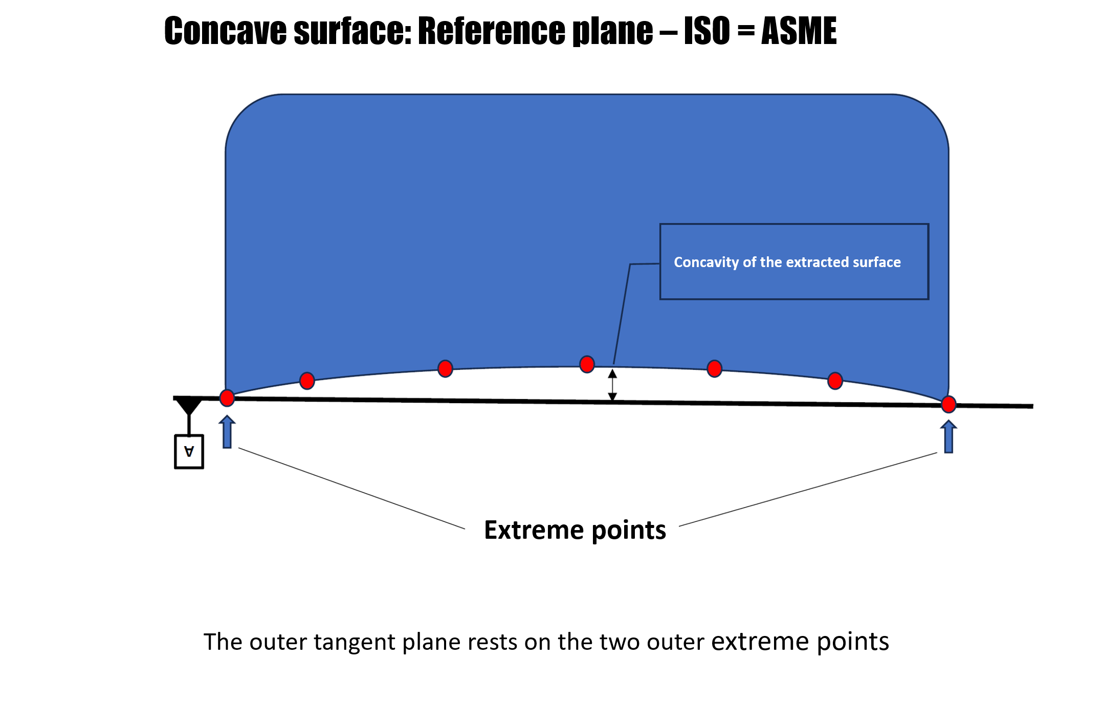
The Case of Concave Surfaces (ISO = ASME) When the extracted surface has a concave shape (a depression towards the inside of the material):
-
ISO (ISO 5459): The datum plane is an outer tangential plane associated via the Chebyshev criterion (minimum zone), translated to the highest points of the material.
-
ASME (Y14.5): The datum plane is also the outer tangential feature related to the contact points.
-
Conclusion: In the case of concavities, both standards lead to the same geometric result.
-
For these practical reasons, most production lines use stable alignments based on LSQ (or RPS points) for the base system of the program, while the strict calculation rules according to ISO 5459 are activated individually on the GD&T characteristics where the standard explicitly requires it on the technical drawing.
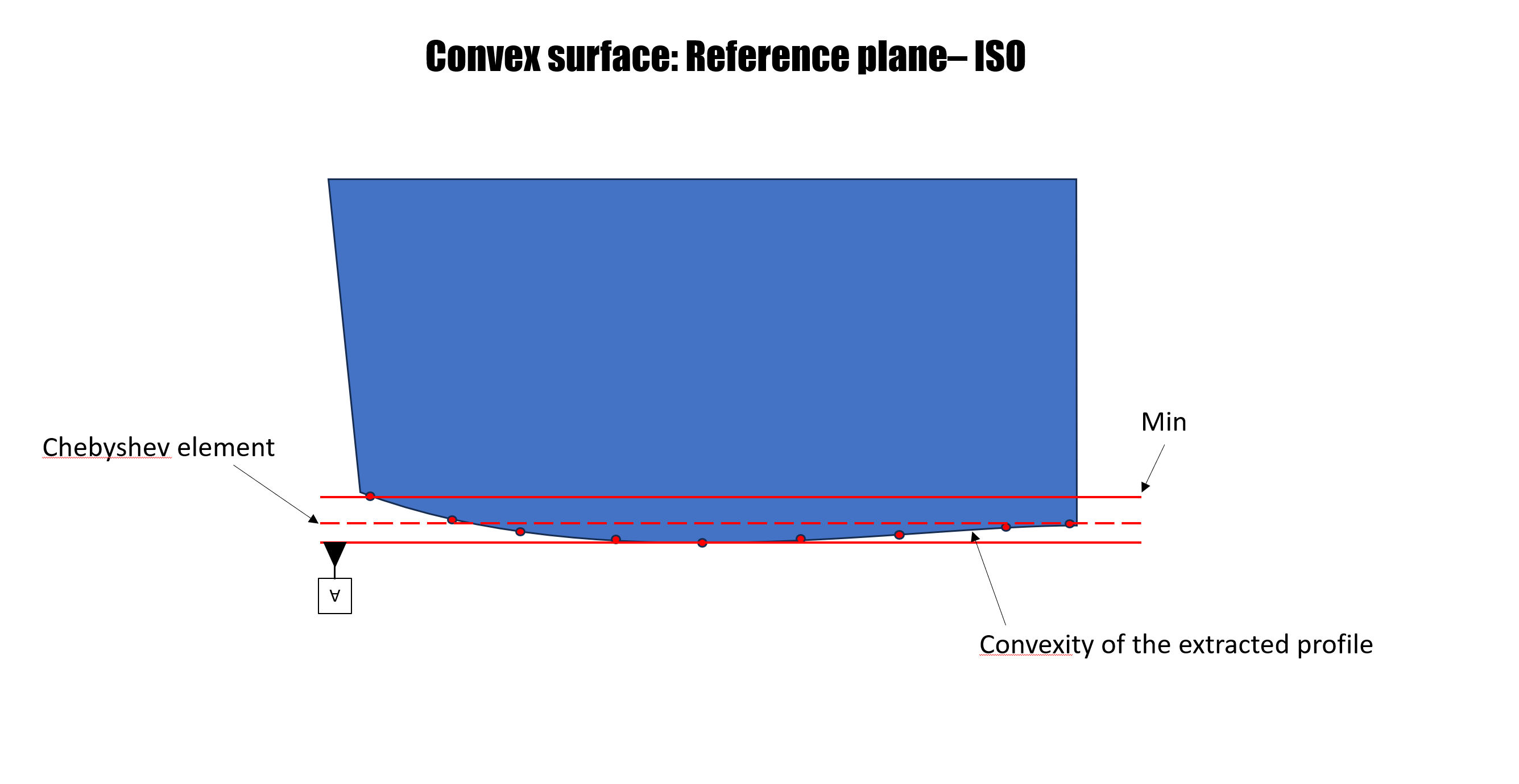
The Case of Convex Surfaces (ISO ≠ ASME) The major divergence appears when the part presents a convex shape (bowed outward):
-
The ISO Standard (Chebyshev / Minimum Zone): Associates a single unique plane based on the Chebyshev algorithm, keeping the datum plane parallel to the minimum zone and tangent to the outside of the material.
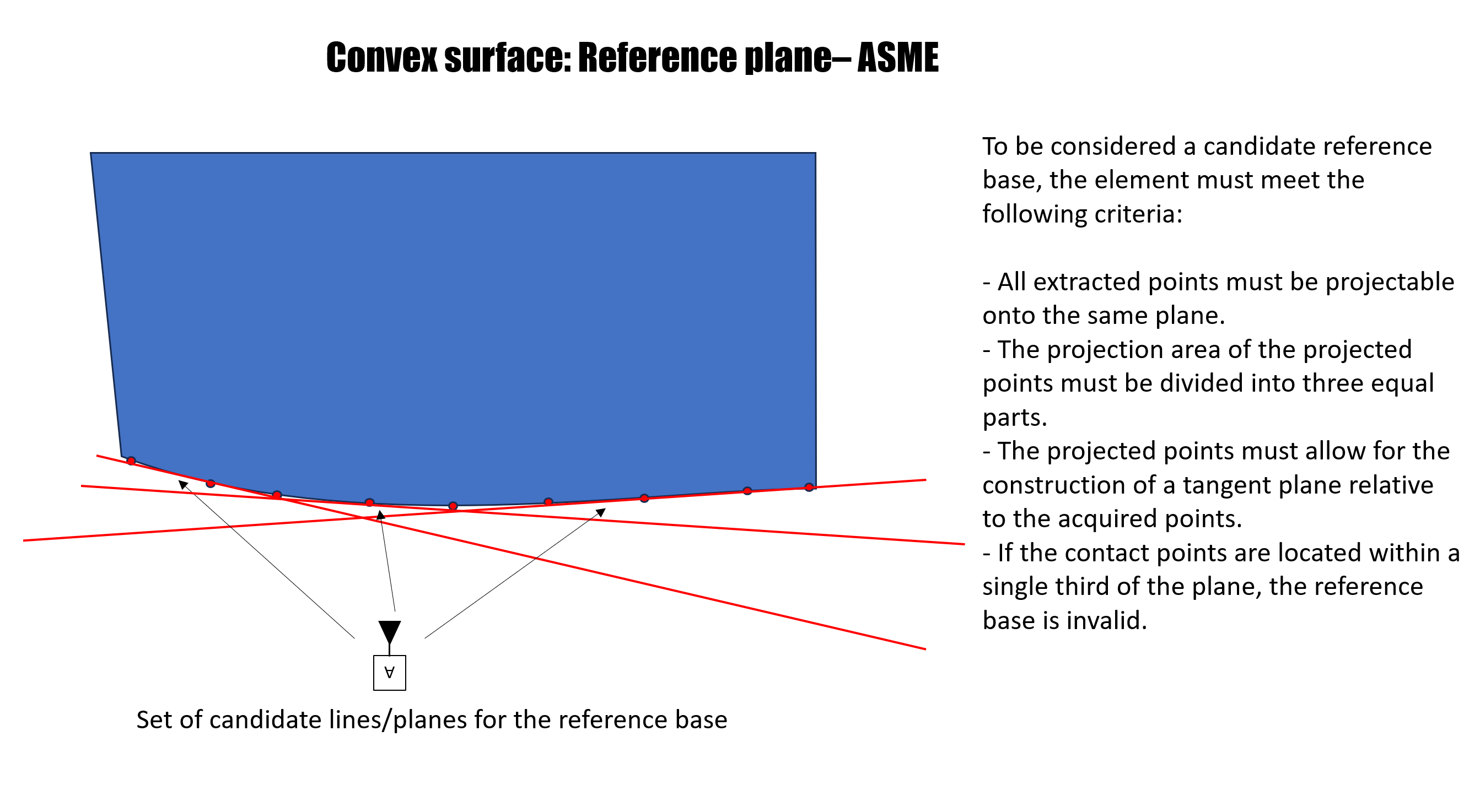
The ASME Standard (Candidate Datum Set): ASME recognizes the physical instability of a part rocking on a convex surface (the "rocking chair" effect). The standard introduces the concept of the Candidate Datum Set — a set of possible tangential planes. A geometric tolerance is considered conforming if the part meets the requirement for any of these candidate planes.
5. The Future: A Controversial New Proposal
Pay attention to future updates in metrology software! Until now, datums have been based on the minimum zone rule (Chebyshev). However, there is a new proposal for the default association in both ISO and ASME.
The ISO/FDIS 5459 (2024) proposal suggests the use of an outer tangential plane that minimizes the distances to the actual surface using the least squares method (Gauss). In the ASME system, a similar, though not completely identical, proposal is under discussion (ASME Y14.5.1-2019 Nonmandatory Appendix B).
-
The filtering method must be taken into consideration when applying these calculations.
-
The deviation from the default association rule can be neglected in the case of a concave surface.
-
Are you facing challenges related to interpreting GD&T tolerances or setting up datum systems for complex parts? At XYZ Architect, we specialize in precision measurement and quality control consulting. Contact us today to ensure your alignments are perfectly anchored in reality.
This shift from Chebyshev to Gauss as the default association will generate different alignment results compared to current ones and remains a controversial topic within standardization committees.
Conclusion
Choosing the correct standard and enforcing the hierarchy (orientation constraints) in the CMM software are not details to be left on "Default" settings. They directly define the acceptance or rejection of your product.