 EN
 Romana
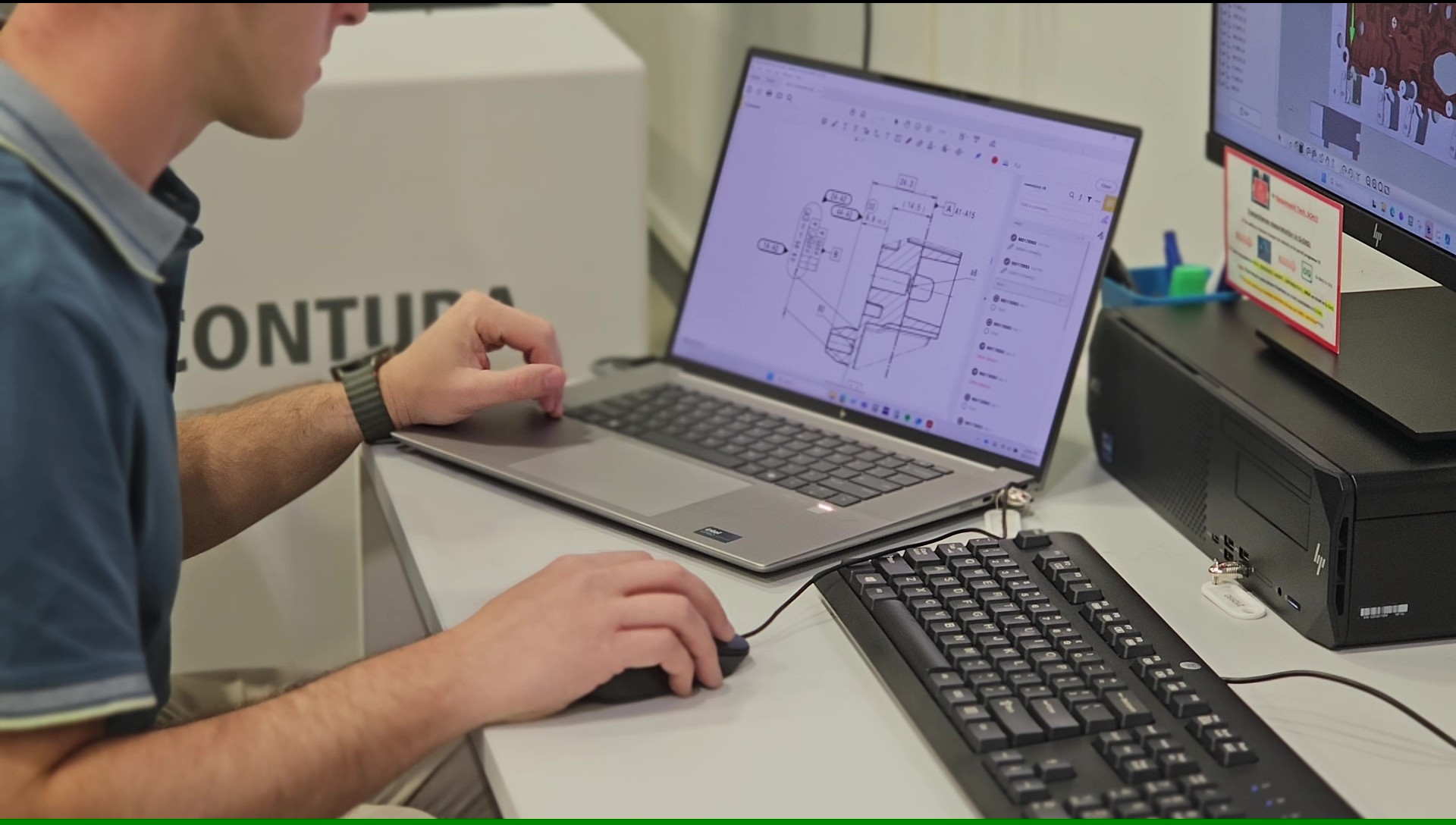
In manufacturing—particularly within the automotive sector—a CMM program left without rigorous review is a guaranteed source of bottlenecks. Whether it leads to the acceptance of non-conforming parts or the rejection of good ones, the costs incurred by a flawed program are immense.
Drawing on 14 years of experience working on measurement process optimization projects, I have found that most discrepancies do not stem from the physical limitations of the equipment, but rather from a superficial initial interpretation and setup of the measurement program.
To ensure a stable and accurate process, every program must undergo strict validation before being deployed in serial production.
Below are the key points that must be verified during the review phase.
1. Validation of Alignments and Datums
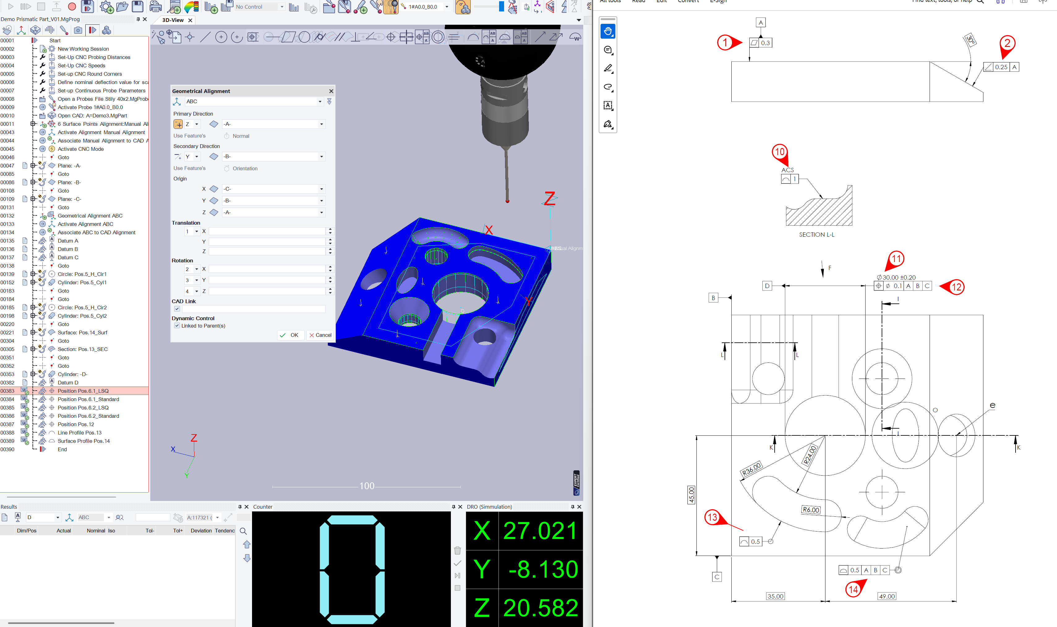
The alignment of the part on the measuring machine must reflect the design intent on a 1:1 basis. The first check concerns how the datums are constructed and referenced within the program. It must be confirmed that the sequence in which the datums are established (primary, secondary, tertiary) correctly constrains all 6 degrees of freedom, and that any material modifiers are applied exactly as specified in the engineering drawing.
2. Respect of Measurement Strategies and Technical Drawings
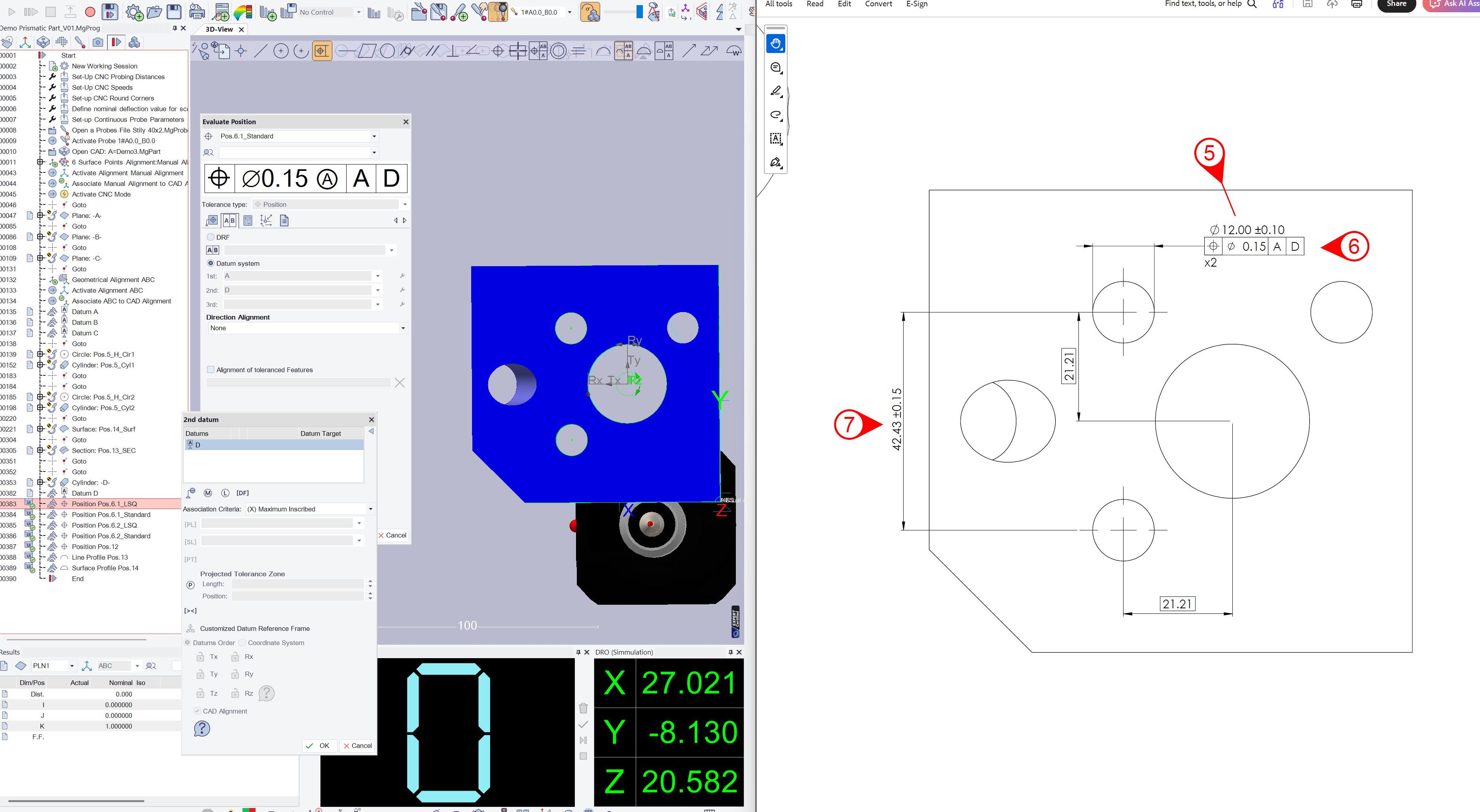
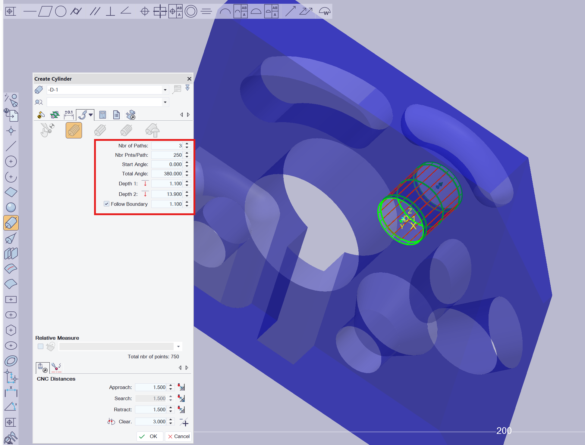
Every geometric tolerance (GD&T or GPS) follows a specific evaluation logic. It must be verified that each feature was measured using the correct elements and that the precise theoretical dimensions were applied to define positional deviations. A common error is evaluating a positional deviation without correctly constraining the feature relative to the datum reference frame specified in the tolerance frame.
A line or a cylinder with significant form deviations cannot be correctly evaluated using only 4 points. The review process must confirm that the number of points collected for each geometric feature is sufficient to accurately capture the actual surface variations, especially when it comes to form tolerances (cylindricity, flatness, circularity, etc.).
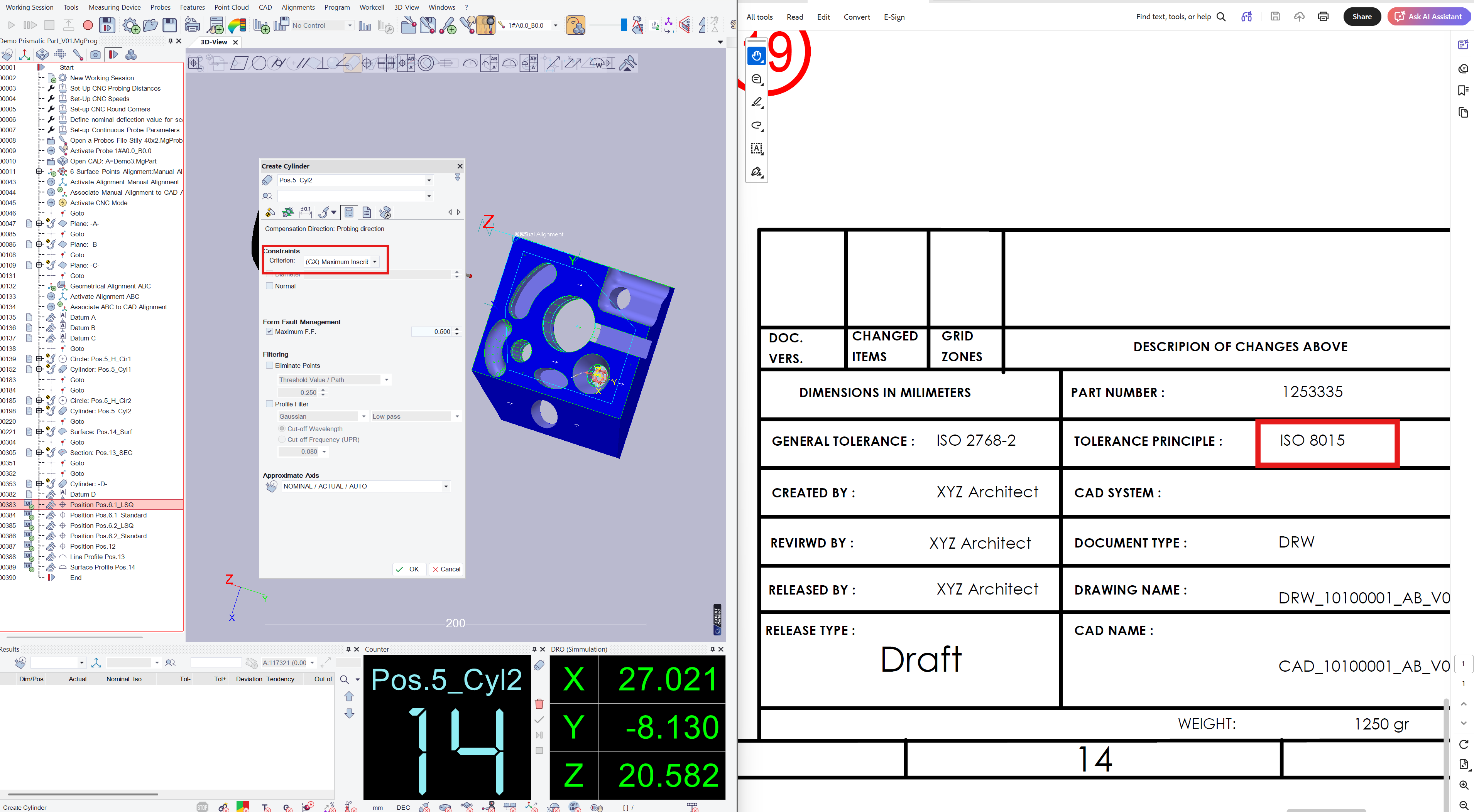
Does the program comply with the ISO or ASME standards specified on the drawing? The fitting method applied to measured features can radically alter the final result. Verify that the programmer has used the method appropriate for the part’s intended function—for instance, a Gaussian (Least Squares) fit for determining centers, versus an ideal mating feature (e.g., Maximum Inscribed Cylinder / Minimum Circumscribed Cylinder) for assemblies.
5. Dynamics: Scanning Speed
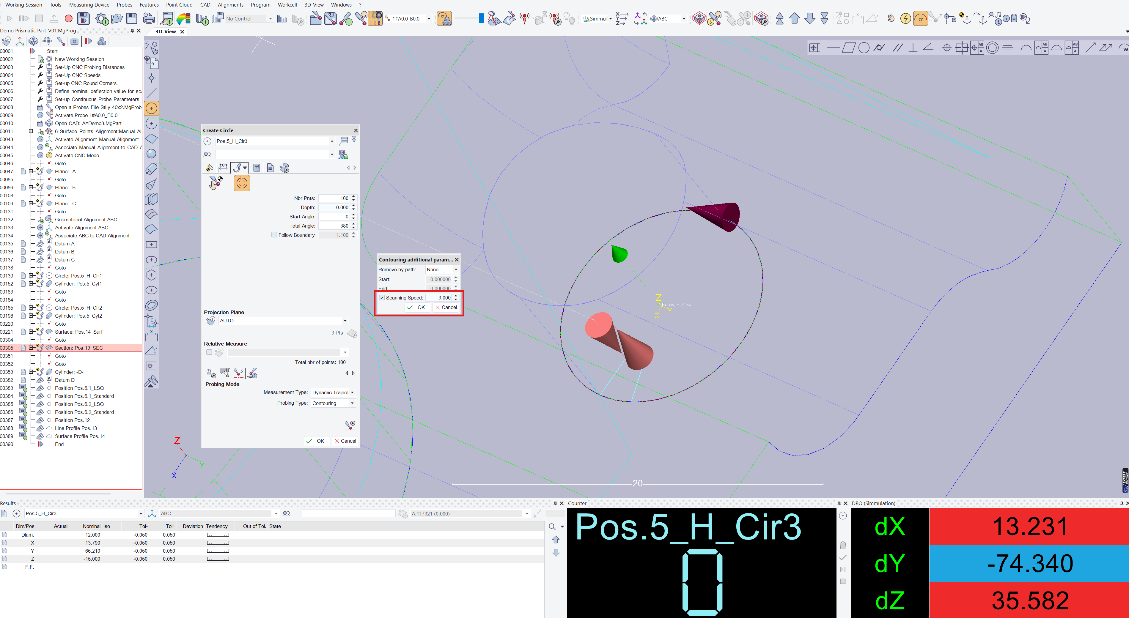
An excessively high scanning speed induces inertial forces that lead to elastic deformation of the probe and errors in point recording. Verify that the probing and scanning speed are adapted to the required precision, point density, and the physical characteristics of the probe assembly.
An excessively high scanning speed induces inertial forces that lead to elastic deformation of the probe and errors in point recording. Verify that the probing and scanning speed are adapted to the required precision, point density, and the physical characteristics of the probe assembly.
6. Data Filtering and Outlier Management
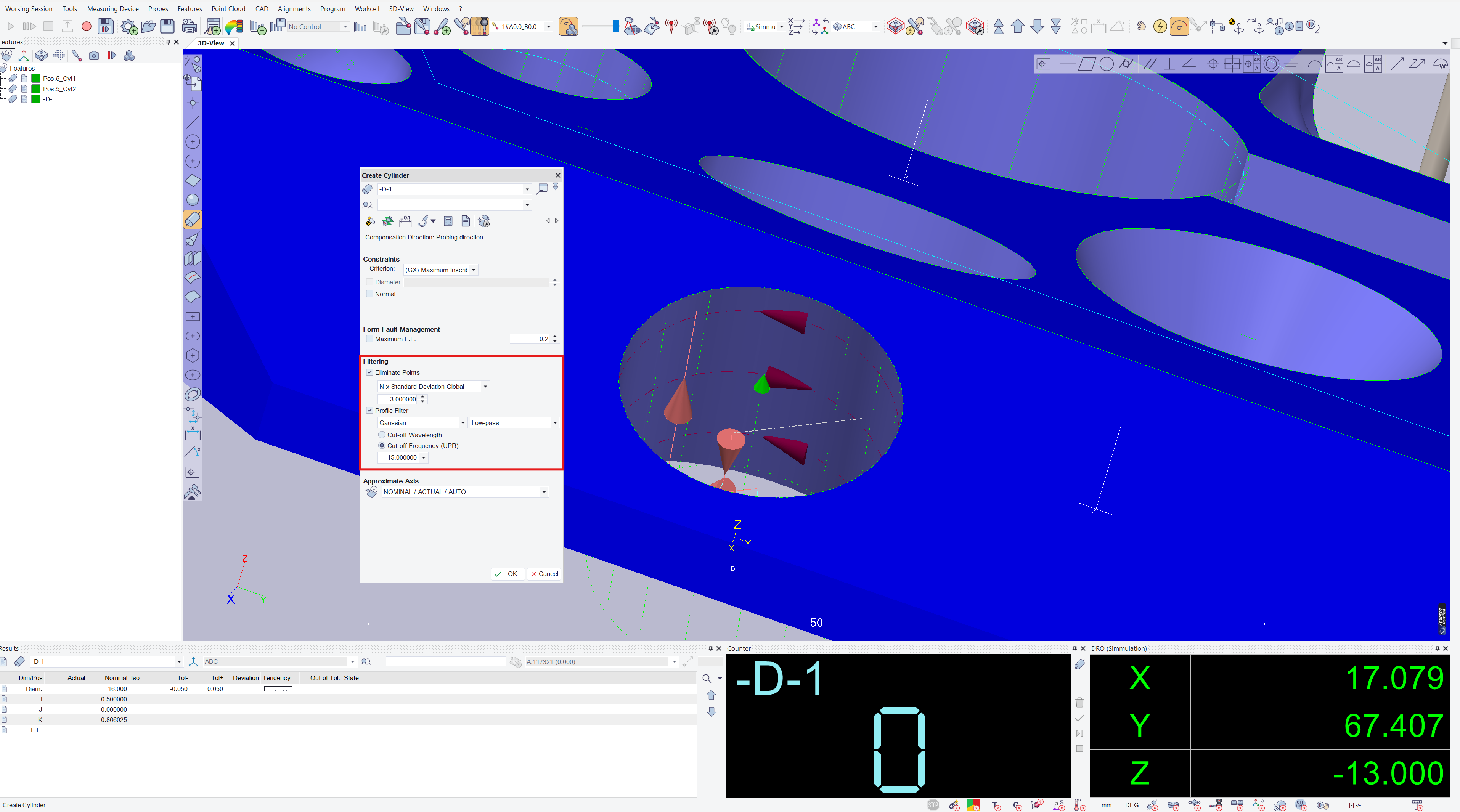
Small burrs, dust, or scratches often appear on (CNC) machined surfaces. The software must include clear settings for removing outliers (anomalous data points) prior to the calculation of features. Furthermore, the settings for mathematical filters (e.g., Gaussian filters, the number of UPR—undulations per revolution—for waviness features) must be aligned with the applicable standards, so as to avoid inadvertently "smoothing out" actual defects on the part.
Small burrs, dust, or scratches often appear on (CNC) machined surfaces. The software must include clear settings for removing outliers (anomalous data points) prior to the calculation of features. Furthermore, the settings for mathematical filters (e.g., Gaussian filters, the number of UPR—undulations per revolution—for waviness features) must be aligned with the applicable standards, so as to avoid inadvertently "smoothing out" actual defects on the part.
7. Physical Configuration of the Probe
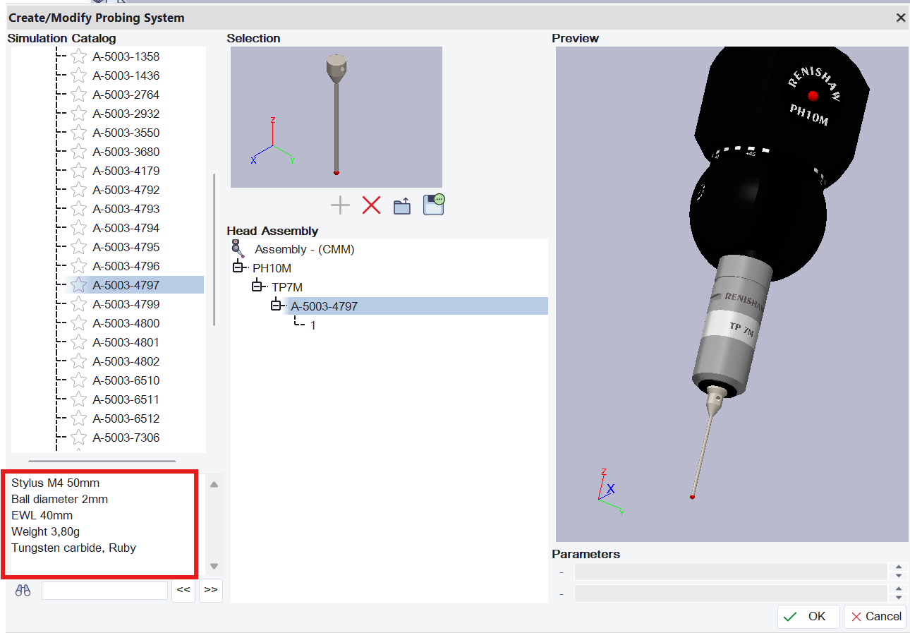
- Mechanical errors are the most difficult to compensate for via software. The physical configuration must be analyzed within the program:
- Diameter-to-length ratio: The probe stylus should not be unnecessarily long or thin (e.g., a 1 mm probe tip on a 50 mm stylus). Such configurations flex and generate vibrations that compromise scanning accuracy.
- Probing angles: The positions of the articulating head must be selected so that the probe approaches the surface either perpendicularly or at a 45-degree angle.
Avoiding "shanking": Ensuring that the chosen probing angles prevent the stylus—rather than the ruby sphere—from coming into contact with the workpiece (the primary cause of false dimensional errors).
- Mechanical errors are the most difficult to compensate for via software. The physical configuration must be analyzed within the program:
- Diameter-to-length ratio: The probe stylus should not be unnecessarily long or thin (e.g., a 1 mm probe tip on a 50 mm stylus). Such configurations flex and generate vibrations that compromise scanning accuracy.
- Probing angles: The positions of the articulating head must be selected so that the probe approaches the surface either perpendicularly or at a 45-degree angle.
Avoiding "shanking": Ensuring that the chosen probing angles prevent the stylus—rather than the ruby sphere—from coming into contact with the workpiece (the primary cause of false dimensional errors).
8. Calibration Status and Thermal Compensation
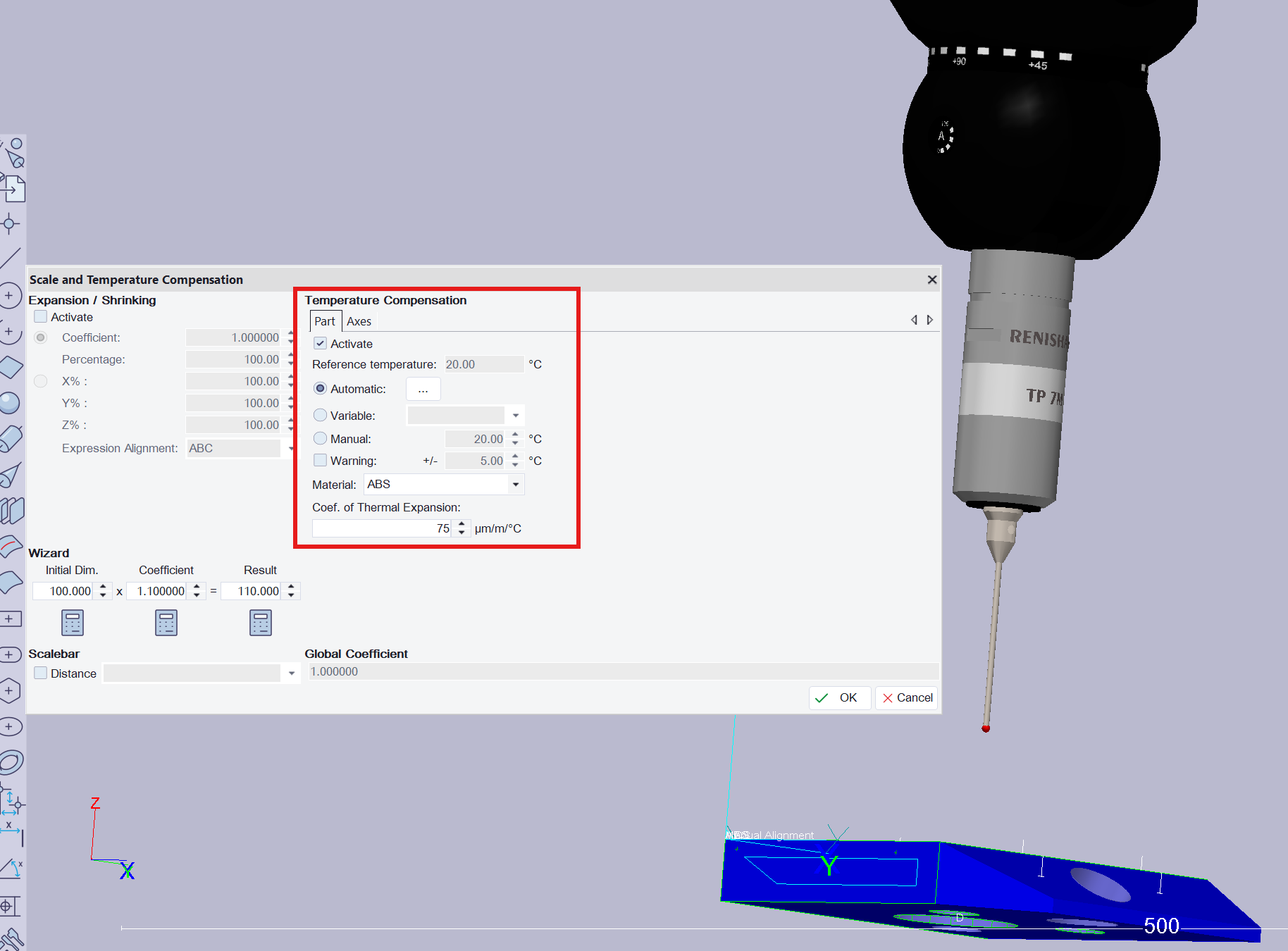
A theoretically perfect program will fail if the physical environment is not controlled. The final review must confirm that the program includes the correct calls for recently calibrated sensors and that thermal compensation functions are enabled, with the workpiece material and reference temperature clearly defined.
A theoretically perfect program will fail if the physical environment is not controlled. The final review must confirm that the program includes the correct calls for recently calibrated sensors and that thermal compensation functions are enabled, with the workpiece material and reference temperature clearly defined.
Implementing such a checklist transforms CMM programming from a source of stress into an absolute quality filter.
If you need support in auditing existing programs or establishing a clear metrology strategy within your quality department, at XYZ Architect, we can analyze and optimize your entire measurement workflow.