

Due to the great distance between suppliers, this is impossible. How do we guarantee mountability without having both parts in the same location?
The solution lies in establishing stable datums that perfectly simulate the part's clamping condition for both subassemblies. Thanks to datum association methods, both the supplier in France and the one in Italy can check the parts independently, ensuring a perfect fit on the assembly line every single time.

Which Geometric Features Can Be Used as Datums?
In 3D metrology and technical drawing interpretation according to ISO GPS and ASME standards, datums are established using various geometric features. These are divided into three main categories:Planes
 Integral Plane
 Median plane
Lines
 Integral straight line
 Axis of cylinders or cones
Points
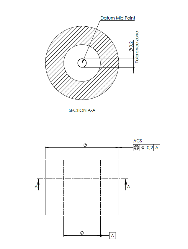
Points resulting from circle intersections, midpoints, integral points, or datum targets.
Standards Note: In the ISO standard, this structure is called a Datum System, while in the ASME standard, it is defined as a Datum Reference Frame (DRF). Both systems use a clear hierarchy: primary datum, secondary datum, and tertiary datum.
Constraining the 6 Degrees of Freedom (DoF) in Space
In order for a CMM programmer or a quality inspector to measure a part repeatably, the complete datum system must constrain (lock) the 6 degrees of freedom of the part in space:
-
3 Translations: Linear movement along the X, Y, and Z axes.
-
3 Rotations: Angular movement around the axes, often denoted as:
-
u – rotation along the X axis
-
v – rotation along the Y axis
-
w – rotation along the Z axis
-
Each type of geometric feature (plane, line, point) has the capacity to lock a specific number of degrees of freedom.
Interactive Simulator: The 6 Degrees of Freedom (DoF)
Unlock the padlocks (🔓) to move the part along unconstrained axes. Lock them (🔒) to simulate a datum constraint.
Why Is This Concept Critical for Your Company?
Without correctly defined datums on technical drawings and accurate simulation in the CMM measurement software:
-
Different suppliers will measure the exact same part in completely different ways.
-
Contradictory discussions will arise between quality and production departments.
-
You risk expensive scrap parts discovered too late, right during final assembly.
If you want to ensure your technical drawings strictly comply with ISO GPS / ASME standards, or if your metrology team needs support creating stable CMM programs, I can help you implement industry best practices.
👉 [Schedule a free initial technical discussion here] to analyze the current context of your measurement lab.
👉 [Check out our practical training courses on GD&T/GPS interpretation] tailored for engineers and technicians.